


Design goal of DC motor drive circuit
1. Function: Is the motor unidirectional or bidirectional? Does it need speed regulation? For one-way motor drive, just use a high-power triode or FET or relay to directly drive the motor. When the motor needs to rotate in both directions, An H-bridge circuit consisting of 4 power components can be used or a double-pole double-throw relay can be used. If speed regulation is not required, just use the relay; but if speed regulation is required, PWM (pulse width modulation) speed regulation can be realized by using switching elements such as triode and FET. Multilayer PCB manufacturer in china.
2. Performance: For the PWM drive motor drive circuit, the main performance indicators are as follows.
1) Output current and voltage range, which determines how much power the circuit can drive.
2) Efficiency, high efficiency not only means saving power, but also reducing the heating of the drive circuit. To improve the efficiency of the circuit, it is possible to ensure the switching state of the power device and prevent common-state conduction (a problem that may occur in the H-bridge or push-pull circuit, that is, both power devices are simultaneously turned on to short-circuit the power supply).
3) The effect on the control input. The power circuit should have good signal isolation at its input to prevent high voltage and large current from entering the main control circuit, which can be isolated with high input impedance or optocoupler.
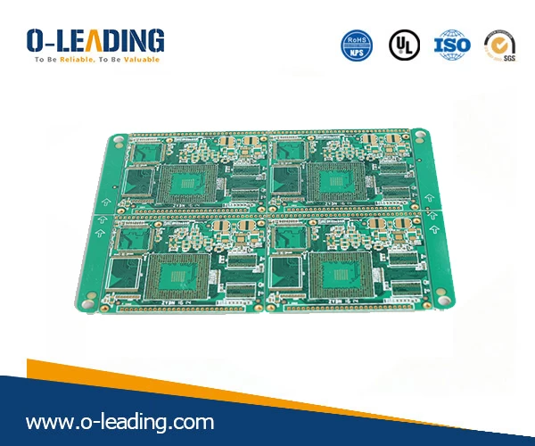
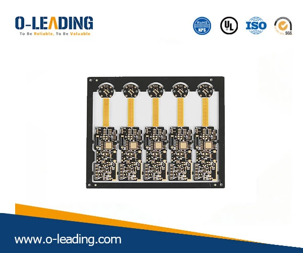
Rigid-flexible PCB with ENIG.
4) The impact on the power supply. Common-state conduction can cause a transient drop in the power supply voltage to cause high-frequency power supply contamination; large currents can cause the ground potential to float.
5) Reliability. The motor drive circuit should be as close as possible, no matter what kind of control signal, what kind of passive load, the circuit is safe.
1. Input and level shifting sections:
The input signal line is introduced by DATA, 1 pin is the ground line, and the rest is the signal line. Note that 1 foot to ground is connected to a 2K ohm resistor. When the driver board and the microcontroller are powered separately, this resistor can provide a path for signal current reflow. When the driver board and the microcontroller share a set of power supplies, this resistor can prevent large currents from flowing along the wires that flow into the ground of the microcontroller board. In other words, it is equivalent to separating the ground line of the driver board from the ground line of the microcontroller to achieve "one-point grounding".
RoHs Compliant manufacturer china.
The high-speed op amp KF347 (also available as TL084) acts as a comparator that compares the input logic signal to a 2.7V reference voltage from the indicator and a diode and converts it into a square wave signal that is close to the power supply voltage amplitude. The input voltage range of the KF347 cannot be close to the negative supply voltage, otherwise an error will occur. Therefore, a diode that prevents the voltage range from overflowing is added to the input of the op amp. One of the two resistors at the input is used to limit current, and one is used to pull the input low when the input is left floating.
The LM339 or any other open-circuit comparator cannot be used in place of the op amp, because the high-level output impedance of the open-circuit output is above 1 kΩ, and the voltage drop is large. The transistor of the latter stage cannot be turned off.
2. Gate drive part:
The circuit composed of the rear triode and the resistor and the Zener tube further amplifies the signal, drives the gate of the FET and uses the gate capacitance of the FET itself (about 1000pF) to delay the FET of the upper and lower arms of the H-bridge. Simultaneous conduction ("common state conduction") causes a short circuit in the power supply.
When the output of the op amp is low (approximately 1V to 2V, which cannot fully reach zero), the lower transistor is turned off and the FET is turned on. The upper transistor is turned on, the FET is turned off, and the output is high. When the output of the op amp is high (approximately VCC-(1V to 2V) and cannot fully reach VCC), the lower transistor is turned on and the FET is turned off. The upper transistor is turned off, the FET is turned on, and the output is low.