


Teach you some tips on EMC design of power PCB
At the same time, the power chip no longer uses only LDOs during the design process, and the use of Buck and Boost power supplies increases. Therefore, the EMC design of the power supply is becoming more and more important. This paper takes a power PCB board as an example to analyze the common problems in the design of the power PCB board. It is hoped that it will provide some ideas for solving the EMC problem of the power module.
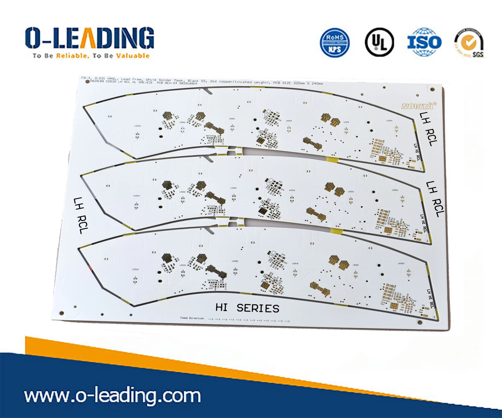
Single PCB manufacturer china.
Design issues:
The power board PCB designed by a hardware engineer is shown in the figure below.
During the EMC design review, the board found that there are a large number of EMC problems and hidden dangers, which need to be revised, otherwise it will face great EMC risks.
Problem 1 The interface filter component is too far from the interface
Problem 2 The interface filter components are not arranged vertically in a row
Problem 3: Power filter components are not arranged together
Problem 4 Switching power supply input and output loop is too large
Impedance PCB manufacturer china.
Design ideas:
The switching power supply board controls the loop area of the input rectification and filtering loop, the power loop, the output rectification loop, and the output filter loop during PCB layout. The loop is small and the wiring is short!
EMC Layout design points
Sensitive signals are kept away from high current signals, especially frequency signals, and should not be routed in parallel.
The current loop traces are as small as possible.
The ground and power grounds need to be separated and can be connected by vias or star points.
Cooper Based PCB in china.
Multi-channel IC power supply, can be connected in parallel with a single point to reduce crosstalk.
The control loop is separate from the power loop.
The decoupling capacitor needs to be placed close to the IC power supply Pin.
The power supply is multi-stage filtered, and the smaller capacitor is close to the chip Pin.
Anti-reverse, clamp-protected devices are placed close to the connector.
Do a good job of isolation design for high voltage and low pressure ground
Pay attention to the spacing of the safety traces