


How to better implement PCB design with EDA tools
o-leading
o-leading.com
2018-07-17 11:08:28
1, determine the number of layers of the PCB
Board size and number of wiring layers need to be determined early in the design process. If the design requires the use of high-density ball grid array (BGA) components, the minimum number of routing layers required for wiring these devices must be considered. The number of wiring layers and the stack-up method directly affect the wiring and impedance of the printed wiring. The size of the board helps determine the stacking and line width to achieve the desired design.
2, design rules and restrictions
The autorouting tool itself does not know what to do. To complete the routing task, the routing tool needs to work under the correct rules and constraints. Different signal lines have different wiring requirements, and all special required signal lines are classified, and different design classifications are also different. Each signal class should have priority. The higher the priority, the stricter the rules. The rules relate to the width of the trace, the maximum number of vias, the parallelism, the interaction between the signal lines, and the limitations of the layers, which have a large impact on the performance of the routing tool. Careful consideration of design requirements is an important step in successful cabling.
3, the layout of the components
To optimize the assembly process, the Manufacturability Design (DFM) rules place restrictions on the component layout. If the assembly department allows the components to move, the circuit can be properly optimized for easier automatic routing. The defined rules and constraints affect the layout design.
To optimize the assembly process, the Manufacturability Design (DFM) rules place restrictions on the component layout. If the assembly department allows the components to move, the circuit can be properly optimized for easier automatic routing. The defined rules and constraints affect the layout design.
4, fanout design
In the fan-out design phase, for the auto-wiring tool to connect the component pins, each pin of the surface mount device should have at least one via so that the board can perform the inner layer when more connections are needed. Connectivity, online testing (ICT) and circuit reprocessing.
In the fan-out design phase, for the auto-wiring tool to connect the component pins, each pin of the surface mount device should have at least one via so that the board can perform the inner layer when more connections are needed. Connectivity, online testing (ICT) and circuit reprocessing.
5, manual wiring and key signal processing
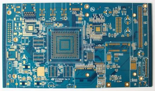
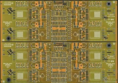
Although this article focuses on the problem of automatic routing, manual routing is an important process for printed circuit board design now and in the future. Manual routing helps the automated routing tool complete the routing work. As shown in FIG. 2a and FIG. 2b, by manually routing and fixing the selected network (net), a path that can be relied upon for automatic routing can be formed.(Printed Circuit Board PCB Manufacturing Company)
Although this article focuses on the problem of automatic routing, manual routing is an important process for printed circuit board design now and in the future. Manual routing helps the automated routing tool complete the routing work. As shown in FIG. 2a and FIG. 2b, by manually routing and fixing the selected network (net), a path that can be relied upon for automatic routing can be formed.(Printed Circuit Board PCB Manufacturing Company)
Regardless of the number of critical signals, these signals can be routed first, manually wired, or combined with an automated routing tool. Critical signals must usually be carefully designed to achieve the desired performance. After the wiring is completed, the relevant engineering personnel will check these signal wirings, which is relatively easy. After the check is passed, the lines are fixed and the remaining signals are automatically routed.
6, automatic wiring
Wiring of critical signals requires consideration of controlling some electrical parameters during routing, such as reducing distributed inductance and EMC, and wiring for other signals. All EDA vendors offer a way to control these parameters. After understanding the input parameters of the automatic routing tool and the influence of the input parameters on the wiring, the quality of the automatic wiring can be guaranteed to a certain extent.
Wiring of critical signals requires consideration of controlling some electrical parameters during routing, such as reducing distributed inductance and EMC, and wiring for other signals. All EDA vendors offer a way to control these parameters. After understanding the input parameters of the automatic routing tool and the influence of the input parameters on the wiring, the quality of the automatic wiring can be guaranteed to a certain extent.