


10 ways to dissipate heat from the PCB must be known!
01
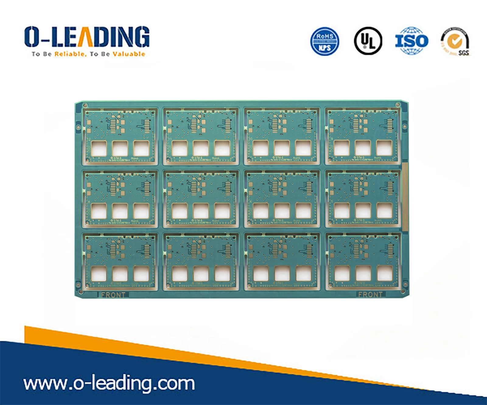
The PCB board which is widely used by the PCB board itself is a copper-clad/epoxy glass cloth substrate or a phenolic resin glass cloth substrate, and a small amount of paper-based copper-clad board is used. Although these substrates have excellent electrical properties and processing properties, they have poor heat dissipation. As a heat dissipation path for high-heat-generating components, it is hardly expected to conduct heat from the resin of the PCB itself, but to dissipate heat from the surface of the component to the surrounding air.
However, as electronic products have entered the era of miniaturization, high-density mounting, and high-heat assembly, it is not enough to dissipate heat from the surface of a component with a very small surface area.
At the same time, due to the large number of surface mount components such as QFP and BGA, the heat generated by the components is transferred to the PCB in a large amount. Therefore, the best way to solve the heat dissipation is to improve the heat dissipation capability of the PCB itself in direct contact with the heat generating components. Conducted out or emitted.
RoHs Compliant manufacturer china.
Heat-dissipating copper foil and copper foil with large area power supply
Hot via
Copper on the back of the IC reduces the thermal resistance between the copper and air
PCB layout
a. The heat sensitive device is placed in the cold air area.
b. The temperature sensing device is placed in the hottest position.
c. The devices on the same printed board should be arranged as far as possible according to their heat generation and heat dissipation. Devices with low heat generation or poor heat resistance (such as small signal transistors, small scale integrated circuits, electrolytic capacitors, etc.) should be placed. The uppermost flow (at the inlet) of the cooling airflow, the device that generates a large amount of heat or heat (such as a power transistor, a large-scale integrated circuit, etc.) is placed at the most downstream of the cooling airflow.
d. In the horizontal direction, the high-power devices are placed as close as possible to the edge of the printed board to shorten the heat transfer path; in the vertical direction, the high-power devices are placed as close as possible to the top of the printed board, so as to reduce the temperature of other devices while the devices are operating. Impact.
High Tg PCB manufacturer china.
e. The heat dissipation of the printed circuit board in the device mainly depends on the air flow, so the air flow path should be studied during the design, and the device or the printed circuit board should be properly configured. When the air flows, it tends to flow in a place with low resistance. Therefore, when configuring the device on the printed circuit board, avoid leaving a large air space in a certain area. The same problem should be noted in the configuration of multiple printed circuit boards in the whole machine.
f. Temperature sensitive devices should be placed in the lowest temperature area (such as the bottom of the device). Do not place it directly above the heating device. Multiple devices are preferably staggered on a horizontal plane.
g. Place the device with the highest power consumption and maximum heat generation near the best position for heat dissipation. Do not place a device with a higher heat on the corners and peripheral edges of the printed board unless a heat sink is placed near it. When designing the power resistor, choose a larger device as much as possible, and have enough space for heat dissipation when adjusting the layout of the printed board.