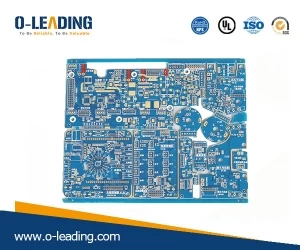
PCB signal integrity issues
o-leading
o-leading.com
2018-07-20 15:24:01

1. Reflection: When the signal is transmitted on the transmission line, when the characteristic impedance of the transmission line on the high-speed PCB does not match the source impedance or load impedance of the signal, the signal will be reflected, causing the signal waveform to overshoot, undershoot and thereby cause Ringing phenomenon. Overshoot is the first peak (or valley) of a signal transition, which is an additional voltage effect above the power level or below the ground level; Undershoot is a signal jump. Change to the next valley (or peak). Excessive overshoot voltage often causes long-term impact damage to the device, undershooting reduces noise margin, and ringing increases the time required for signal stabilization, which affects system timing.
2. Crosstalk: In PCB, crosstalk refers to the undesired noise interference caused by electromagnetic energy to adjacent transmission lines through mutual capacitance and mutual inductance when the signal propagates on the transmission line. It is the electromagnetic field caused by different structures. Produced by interactions in the same area. The mutual capacitance induces a coupling current called capacitive crosstalk; and the mutual inductance induces a coupling voltage called inductive crosstalk. On the PCB, crosstalk is related to the length of the trace, the spacing of the signal lines, and the condition of the reference ground plane.
3. Signal delay and timing error: The signal is transmitted at a limited speed on the PCB conductor, and the signal is sent from the driver end to the receiver end with a transmission delay. Excessive signal delay or signal delay mismatch can cause timing errors and logic device turbulence.
High-speed digital system design analysis based on signal integrity analysis can not only effectively improve product performance, but also shorten product development cycle and reduce development costs. In the case of the development of digital systems in the direction of high speed and high density, it is very urgent and necessary to master this design tool. The digital system design method for computer design and analysis using signal integrity will be widely and comprehensively applied in the continuous improvement and improvement of the signal integrity analysis model and computational analysis algorithm.
High-speed digital system design analysis based on signal integrity analysis can not only effectively improve product performance, but also shorten product development cycle and reduce development costs. In the case of the development of digital systems in the direction of high speed and high density, it is very urgent and necessary to master this design tool. The digital system design method for computer design and analysis using signal integrity will be widely and comprehensively applied in the continuous improvement and improvement of the signal integrity analysis model and computational analysis algorithm.


