


PCB failure analysis case and method
As the hub of various component carriers and circuit signal transmission, PCB has become the most important and key part of electronic information products, and is widely used in various industries. In recent years, there have been more and more cases of PCB failures and some of the failures are extremely harmful. The "Equipment Manufacturing and Standardization and Quality Improvement Plan" and "Made in China 2025" adopted in April 2016 adhere to the basic policy of "innovation-driven, quality-first, green development, structural optimization, and talent-oriented". The quality requirements of the products are getting higher and higher, and the reliability of the products is becoming more and more strict. Therefore, the quality and reliability of the PCB quality determine the quality and reliability of the whole equipment.
Printed circuit boards supplier
In the past, only military products offered reliability requirements, and many civilian products now offer a variety of reliability requirements. Different types of customers, different product applications, the PCB reliability requirements are also completely different. For example, some customers have a PCB reliability requirement of 260 degrees Celsius for ten hours after baking, and still can meet the PCB electrical performance requirements; some customers require the IST cycle of 250 or even 1000 times, the product resistance change rate is less than 10%; Some customers require PCBA products to meet the 30-minute resonance requirement at 25g acceleration.
two. PCB failure case
As we all know, the failure of the product will cause more serious economic loss and quality impact. However, the modes of PCB failure are various and the root causes of failure are different, such as the corrosion failure of PTH hole copper and the open failure caused by the bottom crack of HDI blind hole. , delamination failure, ENIG product hole ring cracks and PCB board short-circuit fire. The processing process is cumbersome and complicated, and it may cause more reasons for its failure. Therefore, how to quickly locate the root cause of PCB failure and optimize the performance of the product has become one of the important topics in the PCB industry. The following is a list of failure analysis cases related to big data calculation, navigation and medical fields in recent years:
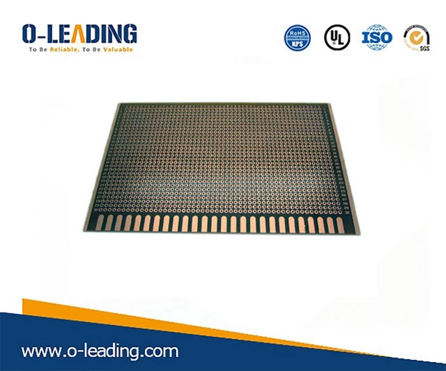
1 PCB burnt board failure
In 2015, a large data center feedback, there will be a fire or burn in one or two pieces of equipment every month, and it is urgent to find the cause of the fire quickly:
Observing the failure site, the burning point of the burning plate is concentrated in the mounting hole area of the hard disk connector, and the copper layer of the hole wall and the positioning tin column in the mounting hole area are completely burned. The analysis found that the NPTH pore wall metallized, during the power-on work, CAF failure occurred, eventually leading to short-circuit fire.
CAF growth principle: When PCBA is charged and operated under certain temperature and humidity conditions, there may be a CAF between the two insulated conductors along the interface between the resin and the glass fiber, which eventually leads to poor insulation and even short circuit failure. The principle of CAF generation is as follows:
There are three prerequisites for CAF: 1 certain temperature and humidity conditions; 2 potential difference between two insulation conduction; 3 channel for copper ion migration.
Experimental recurrence: The tester's insulation resistance failure module is subjected to a 12V voltage-stabilization test. The test board is short-circuited and fired at the moment of power-on, and the sample is continuously ignited and carbonized (the test has video recording);
Improvement plan: 1 increase the inner and outer hole ring to conductor spacing design to 300μm; 2 replace the high Tg substrate to ensure good heat resistance and CAF resistance.
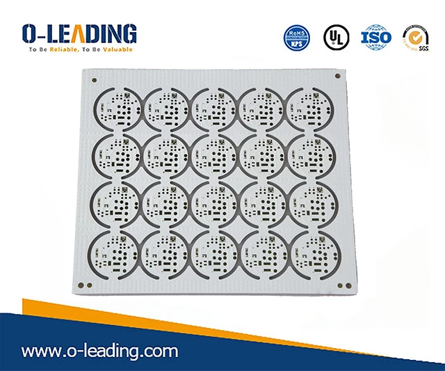
2 Chemical nickel-plated gold plate hole ring crack failure
In 2017, a multinational SMT placement customer feedback, after the reflow soldering of the PTH holes of all ENIG boards purchased in the industry, the test hole ring ring appeared black and black, the probe test could not pass, the whole line was stopped, and the failure analysis was needed. .
In addition to affecting the contact performance of the probe, crack defects in the PTH hole can also cause corrosion of the copper layer, reduce the corrosion resistance of the PCB, and also bring greater risk of failure to the solderability of the product.
The mechanism of crack generation: Due to the principle of thermal expansion and contraction, the PCB board is subject to high temperature expansion during reflow soldering and wave soldering. Since the PCB board selection does not match the surface treatment process, the sheet will give the hole ring an upward stress and the hole will be The ring is lifted up, causing the ring ring to deform toward both sides, causing cracks in the ring.
Improvement plan: 1 replace the CTE smaller plate; 2 replace the surface treatment process.
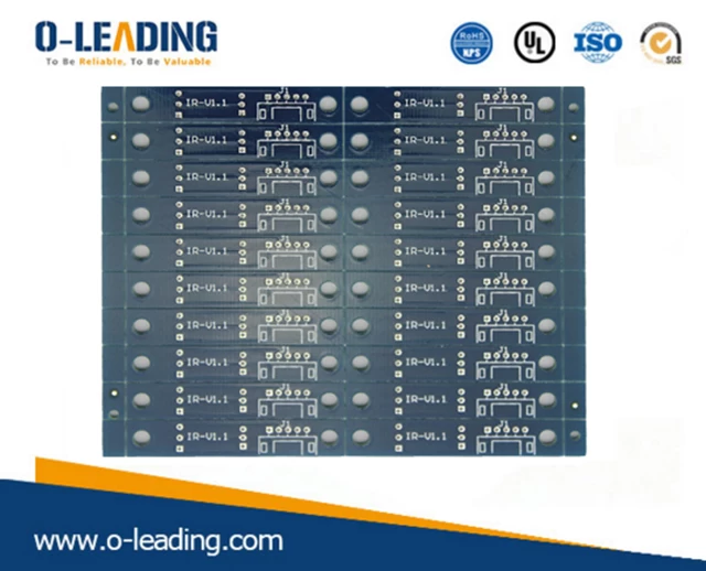
3 PTH hole electrochemical corrosion failure
In 2017, a certain type of 8-layer PCB board, the customer feedback that the whole product is used in the sea and coastal areas for 3 years, there is a phenomenon that the video signal is unreachable, and there is a black foreign matter residue in the PTH hole of the signal abnormal network. Find the root cause and locate the failure point.
The PTH hole covered by the foreign matter was found to have obvious cracks between the solder joint and the copper hole at the hole position of the plug hole, and the hole copper at the crack position was corroded, and some of the hole copper was missing.
At the same time, comparing the normal PTH holes covered by foreign matter on the PCB, it is found that the normal hole internal resistance welding has good bonding with the hole wall, no crack, the hole copper is not corroded, and the signal conduction is good.
According to research, in the high salt and high humidity environment along the coast, a thin layer of water film will be formed on the surface of the object, and when the relative humidity is in the air of 65%-80%, the water film thickness on the object is 0.001~ 0.1μm, when the PCB is working, the water film and the copper hole together form an electrolytic cell, and an electrochemical reaction occurs, eventually producing a black corrosive substance, as shown below:
Conclusion: When the soldering plug hole is not full or the soldering plug hole has crack, the PTH hole copper which is not covered by the solder mask will form an electrolytic cell, and an electrochemical reaction occurs. The hole copper is corroded, which will bring reliability to the PCB. Come to serious risks.
Improvement plan: Improve the fullness of the plug hole and improve the quality of the plug hole.
Of course, the types and modes of failures are varied. The following are examples of other typical PCB board-level failure analysis cases accumulated in the lab:
From the above cases, we can easily find more and more patterns of PCB board failure, and the root causes of failure are also different. Therefore, it is necessary to summarize and refine the general failure analysis ideas and methods, and form a methodology that can be applied to promote the application. In the analysis of actual cases, the problem is achieved with half the effort and quickly locate the root cause.
three. PCB failure analysis method
The method is mainly divided into three parts, which integrates the three parts of the method, which not only helps us to quickly solve the failure problem and locate the root cause in the actual case analysis process; but also can be based on the framework we have established. Engineers conduct training to facilitate learning by all departments.
The following is an explanation of the analysis ideas and methods. The first is to analyze the ideas;
The first step: the "five steps" of failure analysis
The process of failure analysis is mainly divided into five steps: "1 collecting bad board information → 2 failure phenomenon confirmation → 3 failure cause analysis → 4 failure root cause verification → 5 report conclusion, improvement suggestion". Among them, the first step is to understand the failure content, process flow, structural design, production status, usage status, storage status and other information of the defective PCB board, and prepare for the subsequent analysis process; the second step is to determine the failure according to the failure information. Position, judge the failure mode; the third step is to analyze the failure mode, and check the root cause one by one according to the failure root cause fault tree. If the cause cannot be confirmed in the existing fault tree, then it is necessary to study this through the topic project. Class failure problem, and the conclusion of the study is added to the original fault tree, so that the fault tree is continuously enriched and perfected, and the root cause is exhausted, forming an effective cycle pattern of repeated iterative upgrade; then the reproducibility experiment is carried out through step 4 to verify the root cause. The final output failure analysis report gives a targeted improvement to the root cause of failure.
The second step: the failure root cause fault tree is established
Taking the poor weldability of the gold-plated gold plate as an example, the method of establishing a failure analysis fault tree is described:
For the common board-level failure phenomenon of PCB/PCBA, we establish a root cause failure tree of various failure modes, and continue to accumulate, refine and update in actual combat, and iteratively rises in depth and breadth, thus forming a relatively perfect The root cause failure tree analysis process of high-frequency failure modes such as delamination, poor solderability, poor bonding, poor conduction, and poor insulation can help you follow the fault analysis process of the fault tree in subsequent actual combat. The root cause of failure is to solve the problem and get twice the result with half the effort.
The third step: establish a standard library
The standard library file is formed by verifying the root causes of the fault tree. The source of the root cause judgment standard library mainly has several aspects: 1 IPC, GJB, industry standards and other documents; 2 normal product and abnormal product comparison library; 3 research and development project experience, production experience file library. At the same time, summarize and classify the evaluation methods and evaluation criteria involved in each failure root in the fault tree, and summarize the common PCB standards and various anomaly data to form a PCB failure analysis standard library for reference in subsequent cases. .