Analysis of Transmission Line Characteristics and Structure in High-Speed PCB Design
Signals are reflected because the traces on the PCB have a certain impedance, and the impedance on the wire does not match the impedance on the output end, which will cause signal reflection. There is a delay in the signal transmission in the PCB. If the timing does not match, the system will strike. These are all problems due to transmission lines.
Prototype PCB Assembly company china

What is a transmission line
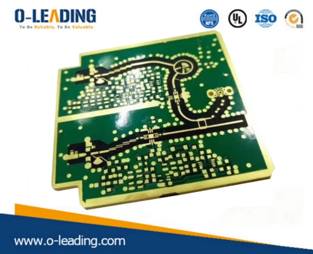
The definition of a transmission line is a signal line that has a signal return, consisting of two wires of a certain length, one is a signal propagation path, and the other is a signal return path. The most common transmission line is the trace on our PCB board.
When analyzing a transmission line, you must contact the return path. A single conductor cannot be a transmission line. Like resistance, capacitance, and inductance, a transmission line is also an ideal circuit element, but its characteristics are very different. It is better for simulation. But the circuit concept is more complicated;
Consigned PCB Assembly factory

Transmission lines have two very important characteristics: characteristic impedance and delay.
Transmission line impedance
Let's clarify a few concepts first. We often see impedance, characteristic impedance, and instantaneous impedance. Strictly speaking, they are different.
But change is inseparable, they are still the basic definition of impedance:
The input impedance at the beginning of the transmission line is simply referred to as the impedance;
The instantaneous impedance encountered by the signal at any time is called the instantaneous impedance;
If the transmission line has a constant instantaneous impedance, it is called the characteristic impedance of the transmission line.
Characteristic impedance describes the transient impedance experienced by a signal as it travels along the transmission line. This is a major factor affecting signal integrity in transmission line circuits. If there is no special description, the characteristic impedance is generally referred to as the transmission line impedance.
Transmission delay
Time delay, also called time delay (TD), usually refers to the time it takes for an electromagnetic signal or an optical signal to pass through the entire transmission medium. The delay on the transmission line is the time it takes for the signal to pass through the entire transmission line.
Propagation delay, also known as propagation delay (PD), usually refers to the time delay of the transmission of electromagnetic or optical signals in a unit length transmission medium. It is inversely proportional (reciprocal) to the "propagation speed". "S / m".
From the definition, we can see:
Delay = propagation delay × transmission length (L)
Edge Plating manufacturer china

Transmission line structure of PCB
The transmission line structure seen in a typical PCB consists of wires that are embedded in or near a dielectric or insulating material and have one or more reference planes. The metal in a typical PCB is copper, and the dielectric is a glass fiber called FR4. The two most common types of transmission lines in digital design are microstrip and stripline.
A microstrip line usually refers to a trace on the outer layer of a PCB and has only one reference plane. There are two types of microstrip lines: buried or non-buried. A buried (sometimes called submerged) microstrip line simply embeds a transmission line in the dielectric, but it still has only one reference plane. A stripline is an inner layer trace between two reference planes.


