


Principle of self-recovering fuse
The self-recovering fuse is an over-current electronic protection component, which is processed by a special process by using a high-molecular organic polymer under the conditions of high pressure, high temperature and vulcanization reaction, after adding conductive particle material. The traditional fuse over-current protection can only be protected once, and it needs to be replaced when it is blown. The self-recovery fuse has over-current over-temperature protection and automatically restores dual functions.
Double Side PCB manufacturer china
working principle
The self-recovering fuse consists of a specially treated polymer resin (Polymer) and conductive particles (Carbon Black) distributed inside. Under normal operation, the polymer resin tightly binds the conductive particles to the crystal structure, forming a chain-like conductive path. The self-recovering fuse at this time is in a low-resistance state (a), and the current flowing through the self-recovering fuse on the line is generated. The heat is small and does not change the crystal structure. When the line is short-circuited or overloaded, the heat generated by the large current flowing through the self-recovering fuse melts the polymer resin, the volume rapidly increases, forming a high-resistance state (b), and the operating current is rapidly reduced, thereby limiting and protecting the circuit. When the fault is removed, the self-recovery fuse re-cools and crystallizes, the volume shrinks, the conductive particles re-form the conductive path, and the self-recovery fuse returns to a low-resistance state, thereby completing the protection of the circuit without manual replacement.
Principle of action
The action principle of the self-recovery fuse is a dynamic balance of energy. The current flowing through the self-recovery fuse generates a certain amount of heat due to the relationship between the current thermal effects (there is a resistance value of the self-recovering fuse), and the generated heat is completely or partially emitted to the environment. The heat that is not emitted will increase the temperature of the self-recovering fuse element. The temperature during normal operation is low, and the heat generated and the heat generated are balanced. The self-recovery fuse element is in a low-resistance state, the self-recovery fuse does not operate, the current flowing through the self-recovering fuse element increases or the ambient temperature rises, but if the generated heat and the radiated heat balance are reached, the self-recovery fuse is still not action. When the current or ambient temperature increases, the self-recovery fuse will reach a higher temperature. If the current or ambient temperature continues to increase, the heat generated will be greater than the amount of heat dissipated, causing the temperature of the self-recovering fuse element to increase rapidly. At this stage, a small temperature change will cause a large increase in resistance. The recovery fuse element is in a high-resistance protection state, the increase in impedance limits the current, and the current drops sharply in a short time, thereby protecting the circuit device from damage, as long as the applied voltage generates enough heat to recover the heat radiated from the fuse element. The self-recovering fuse element in the changing state can always be in the operating state (high resistance). When the applied voltage disappears, the self-recovery fuse can be automatically restored.
Selection
1. Determine the following parameters of the circuit:
a Maximum operating ambient temperature b Standard operating current c Maximum operating voltage (Umax) d Maximum fault current (Imax)
2. Select self-restoring fuse components that can adapt to the maximum ambient temperature and standard operating current of the circuit.
Use the temperature reduction {ambient temperature (°C) operating current (A)} table and select the temperature that best matches the maximum ambient temperature of the circuit. Browse this column to see equal or greater than the circuit's standard operating current value.
3. Compare the maximum electrical rating of the selected component with the maximum operating voltage and fault current of the circuit
Use the electrical characteristics table to verify that the component you selected in step 2 will use the maximum operating voltage and fault current of the circuit. Check the maximum operating voltage and maximum fault current of the unit. Make sure Umax and Imax are greater than or equal to the maximum operating voltage and maximum fault current of the circuit.
4, determine the action time
The action time is the amount of time it takes for this component to switch to a high resistance state when a fault current is present on the entire device. In order to provide the desired protection function, it is important to clarify the working time of the self-recovering fuse element. If the component you selected moves too fast, unusual or harmful actions will occur. If the component moves too slowly, the protected component may be damaged before the component switches to a high resistance state.
A typical operating time curve of 25 ° C is used to determine if the operating time of the self-recovering fuse element is too fast or too slow for the circuit. If yes, return to step 2 to reselect the spare component.
5, verify the ambient operating temperature
Ensure that the minimum and maximum ambient temperatures for the application are within the operating temperature range of the self-recovery fuse element. Most self-healing fuse components operate over the -40°C to 85°C temperature range.
6. Verify the external dimensions of the self-recovering fuse element
Use a form factor table to compare the form factor of your choice of self-recovering fuse to the space conditions of your application.
technical standard
1, rated zero power resistance
The PPTC thermistor should be packaged in zero-power resistance and marked in the outer package. After the withstand voltage and current resistance test, the resistance change rate of each group before the self is very poor δ|Ri after -Ri before /Ri before - (Rj after -Rj before) /Rj before |≤100%
2, PTC effect
It is said that a material has a PTC (Positive Temperature Coefficient) effect, that is, a positive temperature coefficient effect, which only means that the resistance of the material increases with an increase in temperature. For example, most metal materials have a PTC effect. Among these materials, the PTC effect appears as a linear increase in resistance with increasing temperature, which is known as the linear PTC effect.
3. Nonlinear PTC effect
The phase-change material exhibits a phenomenon in which the resistance increases sharply along the narrow temperature range by several to ten orders of magnitude, namely the nonlinear PTC effect. A considerable number of types of conductive polymers exhibit this effect, such as polymeric PTC thermistors. These conductive polymers are very useful for making overcurrent protection devices.
4, the initial resistance Rmin
Tested at ambient temperature of 25 ° C before being installed in the circuit, the resistance of the polymer PTC thermistor of the self-resetting fuse series.
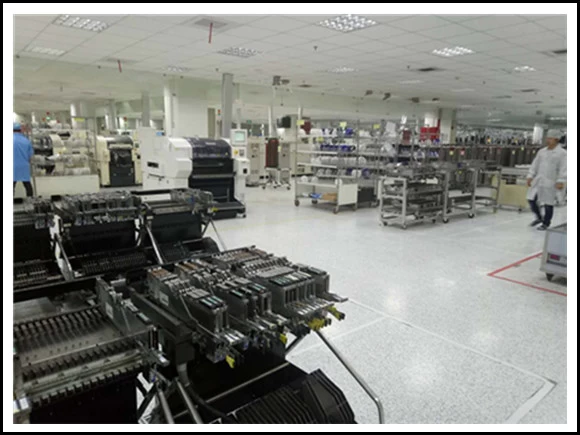
Factory SMT
5, Rmax
Self-resetting fuse series polymer PTC thermistor action or reflow soldering at room temperature
The maximum resistance measured after one hour of installation in the board.
6, the minimum resistance (Rmin) / maximum resistance (Rmax)
At a specified ambient temperature, for example: 25 ° C, the resistance of a specific type of self-resetting fuse series of polymer thermistors before installation to the circuit will be within a specified range, ie at the minimum (Rmin) and maximum (Rmax) )between. This value is listed in the resistance bar in the specification.
7, maintain current Ihold
The holding current is the maximum current that can be passed when the self-resetting fuse series polymer PTC thermistor remains inoperative. Under limited environmental conditions, the device can remain indefinitely long without transitioning from a low resistance state to a high resistance state.
8, action current Itrip
The minimum steady-state current that causes the self-resetting fuse series of polymer thermistors to operate for a limited time under defined environmental conditions.
9, the maximum current Imax (flow resistance)
In the limited state, the maximum operating current of the safety action of the self-resetting fuse series polymer PTC thermistor, that is, the resistance value of the thermistor. Above this value, the thermistor may be damaged and cannot be recovered. This value is listed in the Resistance to Flow column of the specification.
10, leakage current Ires
The self-resetting fuse series polymer PTC thermistor locks the current through the thermistor when it is in its high-impedance state.
11, the maximum working current / normal operating current
The maximum current flowing through the circuit under normal operating conditions. At the maximum ambient operating temperature of the circuit, the holding current of the self-resetting fuse series polymer PTC thermistor used to protect the circuit is generally larger than the operating current.
12, action
Self-resetting fuse series polymer PTC thermistor changes from low resistance to high resistance when overcurrent occurs or ambient temperature increases.
13, action time
The time required for the overcurrent to start until the thermistor is completed. For any particular self-resetting fuse series of polymer PTC thermistors, the greater the current flowing through the circuit, or the higher the operating ambient temperature, the shorter the operating time.
14, Vmax maximum voltage (withstand voltage value)
Under the limited conditions, the self-resetting fuse series polymer PTC thermistor can safely withstand the highest voltage. That is, the withstand voltage value of the thermistor. Above this value, the thermistor may be broken down and cannot be recovered. This value is usually listed in the Pressure Tolerance column of the data sheet.
15, the maximum working voltage
In the normal operating state, the maximum voltage across the ends of the self-resetting fuse series polymer PTC thermistor. In many circuits, it is equivalent to the voltage of the power supply in the circuit.
16. Conductive polymer
Here, it is an electrically conductive composite material obtained by filling an insulating polymer material (polyolefin, epoxy resin, or the like) with conductive particles (carbon black, carbon fiber, metal powder, metal oxide, or the like).
17, ambient temperature
The temperature of the still air around the thermistor or a circuit with the thermistor element.
18, working temperature range
The ambient temperature range in which the P component can operate safely.
19, the maximum working environment temperature
The highest ambient temperature at which the component is expected to operate safely.
20, power consumption
The power consumed by the self-resetting fuse series polymer PTC thermistor is obtained by calculating the product of the leakage current flowing through the thermistor and the voltage across the thermistor.

21, high temperature, high humidity aging
At room temperature, measure the change in resistance of the self-resetting fuse series polymer PTC thermistor before and after a relatively high temperature (such as 85 ° C) and high humidity (such as 85% humidity) for a long time (such as 150 hours).
22, passive aging test
At room temperature, measure the resistance change of the self-resetting fuse series polymer PTC thermistor before and after the high temperature (such as 70 ° C or 85 ° C) for a long time (such as 1000 hours).
23, hot and cold blow test
The test results of the change in the resistance of the self-resetting fuse series polymer PTC thermistor before and after the temperature cycle at room temperature. (For example, cycle 10 times between -55 ° C and +125 ° C).
24, PTC strength β
The PTC thermistor has sufficient PTC strength and cannot exhibit NTC. β = lgR 140 ° C / R room temperature ≥ 5 R 140 ° C, R room temperature is the rated zero power resistance value at 140 ° C and room temperature.
25, action characteristics
The PTC thermistor shall be tested for non-operating characteristics before and after the withstand voltage and current resistance tests, and R is the U/I of the thermistor at the time of the non-operating characteristic test, and Rn is the initial zero-power resistance of the rated resistance. Value or retest value.
26, recovery time
The recovery time after the PTC thermistor is operated should be no more than 60S.
27, failure mode test
In the failure mode test, the high-concentration PTC thermistor may be tested or in a failed state, and the allowed failure mode is open or high-resistance, but no low-resistance or open flame shall occur during the whole test.
O-Leading Supply Chain CO., LTD
TEL: + 86-752-8457668
Fax: + 86-4008892163-239121
+ 86-2028819702-239121