


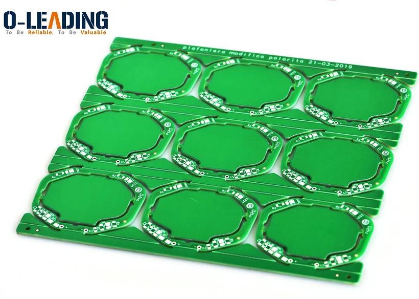
LED Switching Power Supply PCB Circuit Design
The research and development speed of LED switching power supply has made obvious technological leaps in recent years, and the speed of new product upgrades has also accelerated a lot. As the last design link, PCB design is also particularly important, because once there is a problem in this link, it is likely to cause more electromagnetic interference to the entire LED switching power supply system, which is important for the stability and safety of the power supply. Will also cause adverse effects. So, what is the correct PCB design?
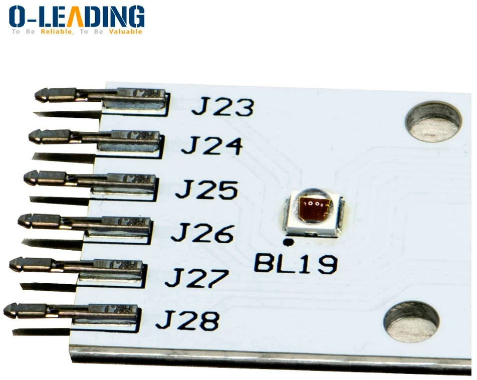
Wireless Light Switch PCB Board Supplier
In recent years, the results of LED power supply component layout research and market practice have proved that even if the circuit schematics designed at the initial stage of research and development are very correct, once the PCB design has problems, it will be detrimental to the reliability of electronic equipment. Influences, such as interference caused by improper consideration of power and ground, will degrade the performance of the product. Therefore, when designing the PCB board, it is necessary to adopt the correct method.
In a PCB board commonly used in switching power supplies, usually each switching power supply has four current loops, which are input signal source current loop, power switch AC loop, output rectifier AC loop, and output load current loop. The input circuit charges the input capacitor through an approximate DC current, and the filter capacitor mainly acts as a broadband energy storage.
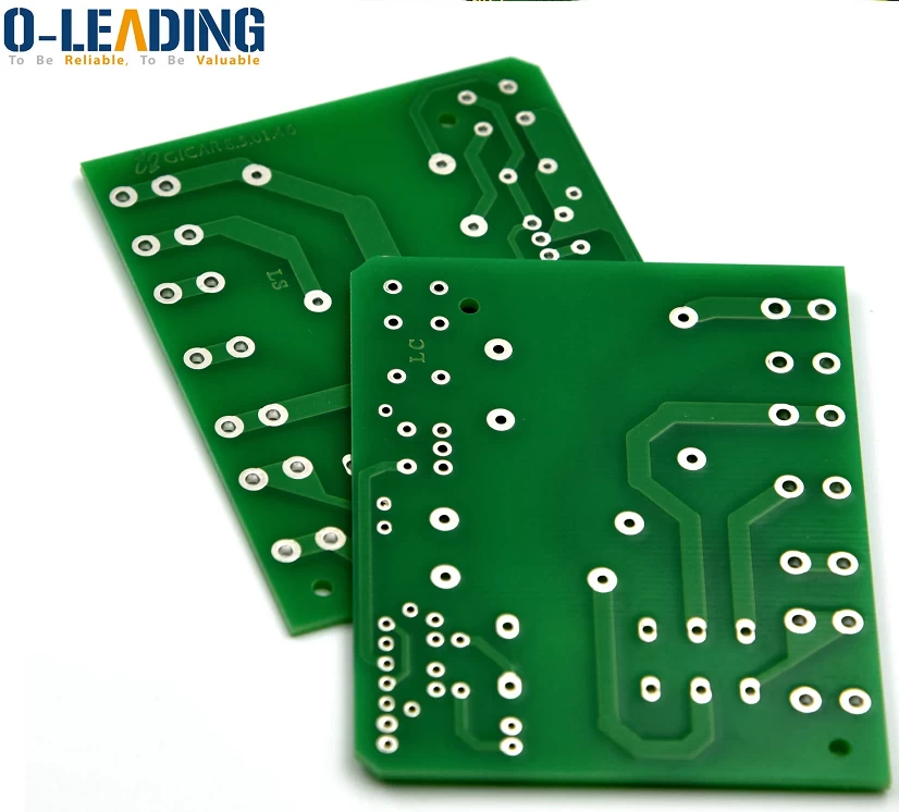
Wifi Smart LED Strip IP65 Waterproof Board Supplier
Similarly, the output filter capacitor is also used to store high-frequency energy from the output rectifier, while eliminating the DC energy of the output load loop. Therefore, the terminals of the input and output filter capacitors are very important. The input and output current loops should only be connected to the power supply from the terminals of the filter capacitor.
The setting and connection of input and output circuits are very important to the entire printed circuit board, and whether it is reasonable or not will directly affect the magnitude of electromagnetic interference. If the connection between the input and output circuits and the power switch and rectifier circuit cannot be directly connected to the terminals of the capacitor, the AC energy will be radiated into the environment by the input or output filter capacitor.
TV Backlight CE ROHS 5V 12V USB Strip LED Flexible Strip
The AC loop of the power switch and the AC loop of the rectifier contain high-amplitude trapezoidal currents. The harmonic components of these currents are very high. The frequency is much greater than the fundamental frequency of the switch. The peak amplitude can be up to 5 times the amplitude of the continuous input and output DC current. About 50ns. These two loops are most prone to electromagnetic interference, so these AC loops must be laid out before other printed wires in the power supply are wired.
In the input and input circuits of the LED switching power supply, each circuit is composed of three main components, which are filter capacitors, power switches or rectifiers, inductors or transformers. These three important components should be placed next to each other, adjusting the position of the components to make the current path between them as short as possible.