


How to test electronic component diodes
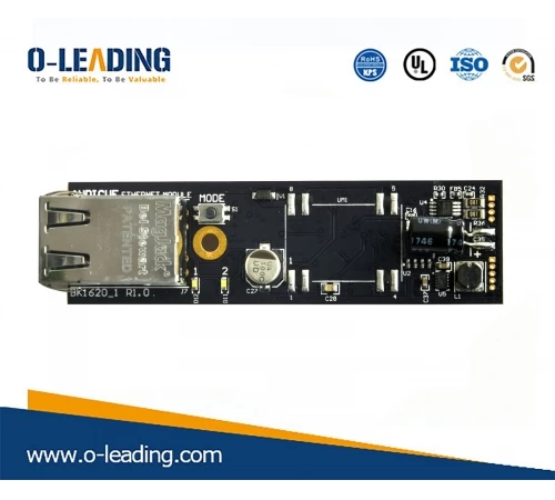
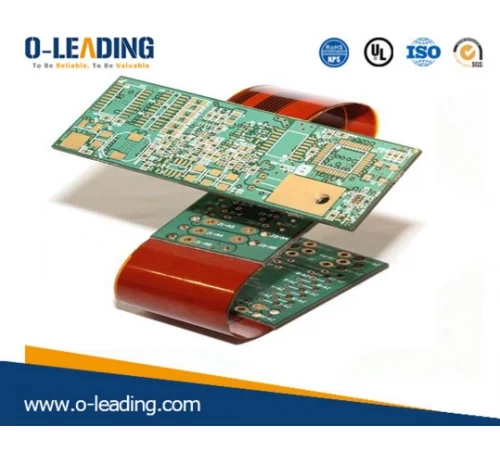
Multi Layer PCB manufacturer china
First, detecting low power crystal diodes
1. Discriminate between positive and negative electrodes: Observe the symbol marks on the outer casing. The diode symbol is usually marked on the outer casing of the diode, with one end with a triangular arrow being the positive pole and the other end being the negative pole. Observe the color point on the outer casing. On the housing of the point contact diode, it is usually marked with a polar color point (white or red). Generally, the end marked with a color point is the positive electrode. Other diodes are marked with a color ring, and one end of the color ring is a negative electrode. The first measurement connected to the black test lead is the positive pole, and the end connected to the red test lead is the negative pole.
2. Detect the highest working frequency fM. The operating frequency of the crystal diode, in addition to the relevant characteristics table, is often used in the practice to distinguish the internal contact wire of the diode. For example, the point contact type diode belongs to the high frequency tube, and the surface contact type diode is mostly the low frequency tube. In addition, it can also be tested with a multimeter R×1k block. Generally, the forward resistance is less than 1k, which is mostly a high frequency tube.
3. Detect the highest reverse breakdown voltage VRM. For AC, because of the constant change, the highest reverse operating voltage is the AC peak voltage that the diode is subjected to. It should be noted that the highest reverse operating voltage is not the breakdown voltage of the diode. In general, the breakdown voltage of the diode is much higher (about one time higher) than the highest reverse operating voltage.
Second, the detection of glass-sealed silicon high-speed switching diode
The method of detecting a silicon high-speed switching diode is the same as the method of detecting a normal diode. The difference is that the forward resistance of this tube is large. With R × 1k electrical blocking measurement, the general forward resistance value is 5k ~ 10k?, and the reverse resistance value is infinite.
Third, detection fast recovery, ultra-fast recovery diode
The method of detecting a fast recovery and ultra-fast recovery diode with a multimeter is basically the same as the method of detecting a plastic-sealed rectifier diode. First, use R × 1k block to detect its unidirectional conductivity, generally forward resistance is about 4~5k, reverse resistance is infinite; then use R × 1 block to retest once, generally forward resistance, reverse resistance still For infinity.
Fourth, detecting bidirectional trigger diode
1. Place the multimeter in the R×1k block. The positive and negative resistance values of the bidirectional trigger diode should be infinite. If the meter is used for measurement, the pointer of the multimeter swings to the right, indicating that the tube under test has a leakage fault.
2. Place the multimeter in the corresponding DC voltage block. The test voltage is provided by a megohmmeter. During the test, shake the megohmmeter, and the voltage value indicated by the multimeter is the VBO value of the tube to be tested. Then replace the two pins of the tube under test and measure the VBR value in the same way. Finally, comparing VBO with VBR, the smaller the difference between the absolute values of the two, the better the symmetry of the measured bidirectional trigger diode.
5. Detection of transient voltage suppression diode (TVS)
1. Use the multimeter R×1k block to measure the quality of the tube: For the unipolar TVS, according to the method of measuring the ordinary diode, the positive and negative resistance can be measured. The general forward resistance is about 4kΩ, and the reverse resistance is gigantic. For the two-way polar TVS, any red and black test leads should measure the resistance between the two pins to be infinite. Otherwise, the performance of the tube is poor or damaged.
Sixth, high frequency varistor diode detection
1. Identifying positive and negative poles: The difference between the appearance of high-frequency varistor diodes and ordinary diodes is that their color-coded colors are different. The color-coded color of ordinary diodes is generally black, while the color-coded color of high-frequency varistor diodes is shallow. color. The polarity is similar to that of a normal diode, that is, one end with a green ring is a negative electrode, and one end without a green ring is a positive electrode.
2. Measure the positive and negative resistances to judge whether they are good or bad: the specific method is the same as the method of measuring the normal and reverse resistance of ordinary diodes. When using the 500-type multimeter R×1k block measurement, the normal high-frequency varistor diode is positive. The resistance is 5k?~5.5k?, and the reverse resistance is infinite.
Seven, varactor diode detection
Place the multimeter in the R×10k block. Regardless of how the red and black test leads are measured, the resistance between the two pins of the varactor should be infinite. If during the measurement, the pointer of the multimeter is slightly swayed to the right or the resistance is zero, it indicates that the varactor diode under test has a leakage fault or has broken through. For the varactor diode capacity to disappear or the internal open circuit fault, it is impossible to detect with a multimeter. If necessary, the replacement method can be used to check and judge.
Eight, the detection of monochrome light-emitting diodes
Attach a 1~5V dry battery to the outside of the multimeter and set the multimeter to R×10 or R×100. This connection is equivalent to a 1~5V voltage connected to the multimeter to increase the detection voltage to 3V (the LED's turn-on voltage is 2V). During the test, use the multimeter and the two pens to alternately contact the two pins of the LED. If the performance of the pipe is good, it must be able to emit light normally. At this time, the black test pen is connected to the positive electrode, and the red test pen is connected to the negative electrode.
Nine, laser diode detection
Place the multimeter in the R×1k block. According to the method of detecting the normal and reverse resistance of the common diode, the order of the pins of the laser diode can be determined. However, it should be noted during the detection that since the forward voltage drop of the laser diode is larger than that of the ordinary diode, when the forward resistance is detected, the pointer of the multimeter is only slightly deflected to the right, and the reverse resistance is infinite.
Detection of infrared light-emitting diodes: Identify the positive and negative electrodes of the infrared light-emitting diode. The infrared light-emitting diode has two pins, usually the long pin is the positive pole and the short pin is the negative pole. Since the infrared light emitting diode is transparent, the electrode inside the tube casing is clearly visible, and the larger one of the inner electrode is the negative electrode, and the narrower one and the smaller one is the positive electrode. Place the multimeter in R × 1k block and measure the positive and negative resistance of the infrared light-emitting diode. Usually, the forward resistance should be around 30k?, and the reverse resistance should be above 500k?, so that the tube can be used normally. The larger the reverse resistance is, the better.

Optical Module manufacturer china
X. Detection of infrared light-emitting diodes
1. Determine the positive and negative electrodes of the infrared light-emitting diode. The infrared light-emitting diode has two pins, usually the long pin is the positive pole and the short pin is the negative pole. Since the infrared light emitting diode is transparent, the electrode inside the tube casing is clearly visible, and the larger one of the inner electrode is the negative electrode, and the narrower one and the smaller one is the positive electrode.
2. Place the multimeter in the R×1k block and measure the positive and negative resistance of the infrared light-emitting diode. Usually, the forward resistance should be around 30k?, and the reverse resistance should be above 500k?, so that the tube can be used normally. The larger the reverse resistance is, the better.
XI. Detection of infrared receiving diode
1. Identify pin polarity: Identify from the appearance. Common infrared receiver diodes appear black in color. When the pin is recognized, facing the light receiving window, from left to right, the positive and negative electrodes, respectively. In addition, there is a small chamfer plane at the top of the tube of the infrared receiving diode, usually the pin with one end of the chamfer plane is the negative pole and the other end is the positive pole. The multimeter is placed in the R×1k block to check the positive and negative electrodes of the common diode for inspection. That is, the red and black test leads are exchanged to measure the resistance between the two pins of the tube. When normal, the resistance should be one. Big one is small. The pin with the red test pen is the negative pole and the pin connected to the black test pen is the positive pole.
2, the detection performance is good or bad. Use the multimeter to block the positive and negative resistance of the infrared receiving diode. According to the magnitude of the positive and negative resistance values, the infrared receiving diode can be preliminarily judged.
o-leading.
You can contact sales@o-leading.com
As a part of our constant efforts toward improvement, we welcome your feedback.
O-leading is all about delivering your printed circuit boards and assemblies on time, and providing excellent quality.
We appreciate your business, and look forward to serving you.