


Attention! The most critical design steps of layout here
Buried vias manufacturer china
But over the years, PCB seems to have been reduced in the field of electronic engineering, becoming an unsung hero who has only quietly paid behind the scenes. Managers believe that PCB layout is a negligible manufacturing problem, not a design engineer needs to care; but with digital circuits Faster and faster RF circuits are placed on the PCB, which has become a limiting factor in many designs. Computer-aided design (CAD) tools can help engineers design boards, but CAD's automatic winding function is usually Will bring more problems.
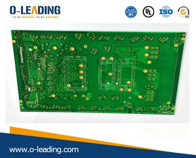
Modern PCBs are not only time killers, but also key components with precise design requirements; the frequency of operation of electronic devices and the rise/fall times of signals are getting faster and faster, so PCBs have become more and more important.
First of all, let's take a look at the following few real stories that have happened, and you will get some inspiration.
A story about the PC motherboard
In 1985, the PC chipset showed a 33MHz bus; Massa received a call from a local PC motherboard manufacturer saying that their new motherboard would not move. The IC supplier's reference design is operational, but the company has made a custom product shape; and Massa noticed that their winding between the components caused the PCB traces to have many sharp angles.
He also found that several key signals were placed in large loops, and there were many vias on the board; those holes allowed the traces to go from the front to the back of the board. The company said that their PCBs were designed by someone in Colorado, USA, and they are cheap and fast, and can be completed in one or two days. Massa told them politely that the wiring was actually made with automated software tools, so the board running the 33MHz signal could never be successfully operated.
The automatic winding tool is very easy to make mistakes. The early PCB software can only ensure the current connection from the signal to the pin. It does not consider the high-speed signal requires a shorter trace. The first required hole or the line width. Problems such as impedance mismatch caused by changes, and finally the entire PCB design fails.
Net Power Module manufacturer china
A story about video chips
In 1995, I had an old brother who worked at a video chip company and had the same situation as before—the reference design was fine, but they had a big Taiwanese customer complaining that their chips could not be operated on the new PCB. And the PCB design has similar wiring errors.
The video chip company faced two choices, one was to confess that the customer's design had problems, please redo, and the other was to make their own video chip a cheap metal mask to compensate for the customer's bad PCB wiring; later They chose the second method, and the customer was of course very happy and felt that they were always right, and they were very satisfied with the customer service that the video chip company sent to them to operate the new chip.
My friend said that this is a sensible strategy for a semiconductor company; the IC industry should import IP for its own chips, rather than paying to teach its customers how to design. You can make some changes in the chip and in turn collect money from customers.
A story about the power supply
When I was a consultant for HP in 1998, I used a Linear SEPIC converter chip LT1513IR in my design; I looked at the product specification sheet and also contacted the Linear Application Engineer Jon Dutra. Said that the wiring diagram in their company specification sheet is wrong.
Dutra, who has now moved to Microsoft, patiently looked at the application examples section of the spec sheet and explained why they suggested deploying the converter in that way. I have several good friends who have retired from Linear, and they have assured me that many of our customers are loyal users of the company's components, because their application engineering support can help customers turn the wrong design into the right; I deployed the SEPIC in the way suggested by Linear, and the first winding was successful.
The laser driver's flexible circuit for DVD recorders requires expertise in PC motherboards or other high-speed, temperature-sensitive designs.
LED Lighting manufacturer china
In general, we make printed board layout design, we must master the following key design elements:
When using PADS or Or CAD to draw schematics, learn about commonly used electronic components in English:
For example, in PCB design, we often use the first three English letters of a part instead of one part itself, like VOL for voltage, RES for resistor, CAP for capacitor, IND for inductor, etc.
The layout must take into account the component layout principles:
In the PCB design, if the circuit system has both digital and analog circuits, the high current circuit must be laid out separately; the input signal processing and output signal drive components ensure that the signal lines are as short as possible; the component spacing is in the medium density board, small components and integration. The component spacing on the circuit chip meets different requirements, etc.
Familiar with several commonly used PCB circuit modules:
For example: i-mode, Bluetooth, Ethernet (LAN), antenna module, HDMI, USB, WIFI and other common modules, will help you quickly design products that meet market requirements;
PCB layout Power and ground handling:
PCB layout Even if the wiring is completed well in the entire PCB design, due to the interference caused by the power supply and ground wire, the performance of the product will be degraded, and even the success rate of the product will be affected;
Implement electromagnetic compatibility to prevent electromagnetic interference (EMI):
Three elements of electromagnetic interference: interference sources, coupling paths, sensitive equipment. Only by first understanding it, it is possible to avoid it and reduce its harm in the circuit.