


Detailed SMT production process
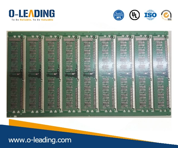
According to the sample BOM placement map provided by the customer, the coordinates of the position of the patch component are processed. Then carry out the first piece with the SMT chip processing data provided by the customer. Net Power Module manufacturer china.
2 Printing solder paste
Printing the solder paste with a steel mesh onto the PCB requires soldering the pads of the electronic component SMD to prepare the solder for the components. The equipment used is a screen printing machine (printing machine), which is located at the forefront of the SMT chip processing line.
3 SPI
Solder paste detector, testing solder paste printing is a good product, with or without less tin, leaking tin, poly tin and other undesirable phenomena.
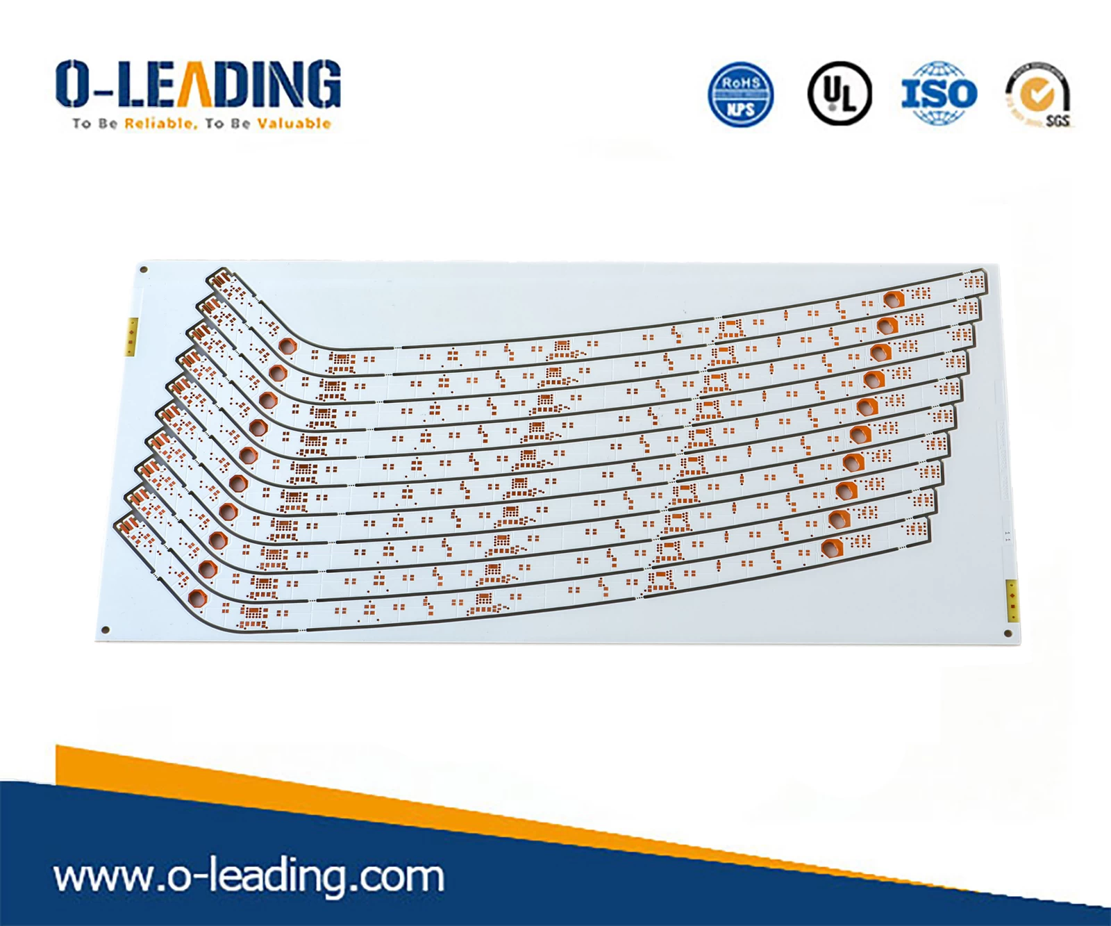
COPPER PASTE FILLING BOARD.
4 Patch
The electronic component SMD is accurately mounted to a fixed position on the PCB. The equipment used is a placement machine located behind the screen printing machine in the SMT production line.
The placement machine is divided into a high speed machine and a general purpose machine.
High-speed machine: for large pin spacing, small components
Universal machine: A component with a small pin pitch (tight pin) and a large volume.
5 High temperature solder paste melting
The main purpose is to melt the solder paste through high temperature. After cooling, the electronic component SMD is firmly soldered to the PCB board. The equipment used is a reflow oven located behind the SMT machine in the SMT production line.
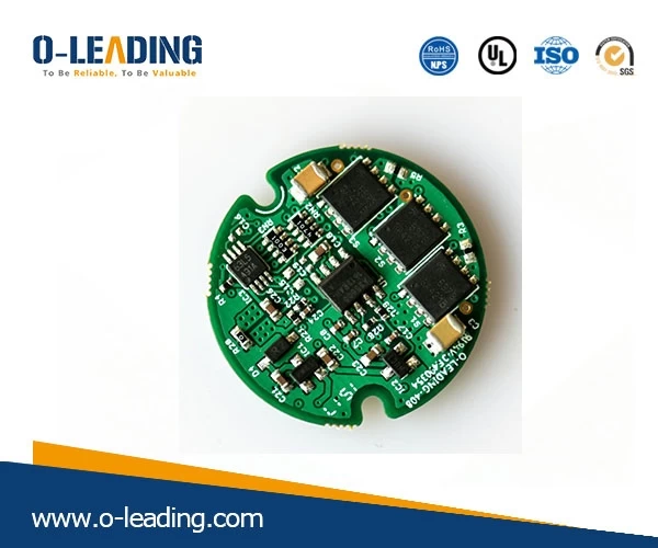
Automotive Power Supply.
6 AOI
Automatic optical detector to detect the welding components after welding, such as tombstoning, displacement, air welding and so on.
7 Visual inspection
Key items of manual inspection and inspection: Whether the version of PCBA is a modified version; whether the customer requires components to use substitute materials or components of designated brands and brands; IC, diode, triode, tantalum capacitor, aluminum capacitor, switch, etc. Whether the direction of the component in the direction is correct; defects after soldering: short circuit, open circuit, false object, false welding.
8 Packaging
Qualified products will be tested and packaged separately. The packaging materials generally used are anti-static bubble bags, electrostatic cotton, and blister disks.
There are two main packaging methods. One is to use an anti-static bubble bag or an electrostatic cotton to form a roll, and the package is separated. It is currently the most commonly used packaging method; the second is to customize the plastic disk according to the size of the PCBA. A PCBA board that is placed in a blister tray and is mainly sensitive to the needle and has a fragile patch component.